
Rebuilding your Weber 40 IDTP Carburetor.
The accelerator pump circuit is a huge part of how your Weber Carburetor performs. Setting up the linkages correctly will mean smooth acceleration. We go over the updated parts you can use.

In this lesson, we cover the accelerator pump. This will lead us to the setup and drilling of the throttle shafts. Putting in all of the jetting, and finally, the discharge volumes, and how to set them.
Assembling the pump
Starting with the studs, use the double nut method to install the studs. The top of the pump uses short studs, with the longer studs in the bottom of the pump. The shorter part of the thread goes into the carburetor body.
Place the smaller of the two pump springs in the housing, then followed by the disc. Put the rubber gasket without the center disc next. Before installing the accelerator pump block, it should be checked for flat.
Some of the tools we use


Flattening the accelerator pump blocks
The accelerator pump blocks are made of soft zinc alloy. They tend to lose a flat surface from time and over-tightening. We use our glass sheet with 80 grit sandpaper to work the surface flat again.
The cover is generally much worse than the pump block. You will tell with the first light sand, as it will show the high points! Work on the parts till they are flat.
Pump Block
The pump block goes on with the pins down, make sure they go through the holes on the gasket. The larger of the two pump springs goes on and the accelerator pump diaphragm. The pin faces out on the diaphragm.
When you put on the cover you need to relive the spring pressure on the gaskets. This is done by holding down the pump diaphragm with a small flat blade screwdriver.
Accelerator pump lever
Make sure your pump lever is not worn out. If you have sent it to plate it may need cleaning to spin freely. We lubricate the lever with Lanox, a light lubricant. Place the retaining pin in place and squeeze the last part in with some channel locks. The pin splines cut into the cover.
The accelerator pump cams have two different shapes. The early cams have a more rounded profile, the later model has a sharper profile. We like the one shaped more like an “ax”. The ax shape brings the fuel on quickly.

The pump cams are held by a specialty shouldered bolt. Leaving it loose then installing the small cotter pin, means when you tighten it, it will face the right direction to fold over.
Accelerator linkage
The accelerator pump linkage you are using should be an adjustable type. If you are using an original, there will be a crimped section on the rod. If you are using an aftermarket linkage, there will be a small washer and e-clip to attach the rod.
At this point, you are ready to drill your new throttle shafts for the pump linkage. Using a 2mm drill, we set the carburetor up in our mill. Be careful to go through straight. Make sure you go all the way through!
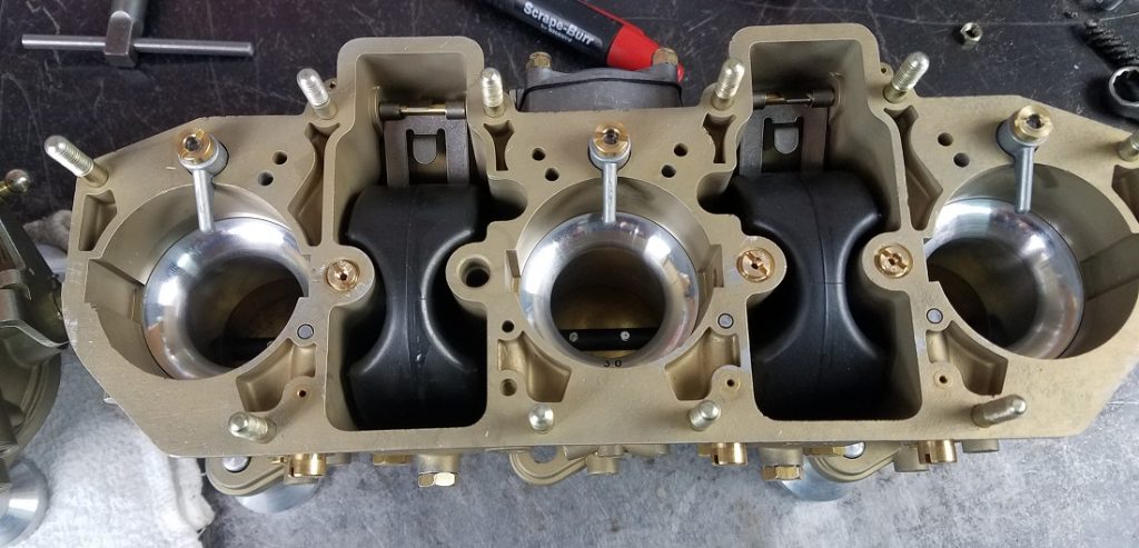
Putting the Jet Package into your Weber Carburetor
Put in the progression port plugs and your accelerator pump check valves. On this carburetor, the check vales are .000. this means they do not allow any fuel to by-pass.
Next, load up your jet package. Choke size is the basis for your jet package. Line up the dimple in the choke to the holding screw. Do not overtighten this screw. We will put in the tie-wires later on.

Continue with the main jets, by placing the main jets into the main jet holders. Use quality tools to work on your carburetor. The seals on the main jets are copper, and are a crush washer, meaning limited re-use. Use fresh washers when re-building.
Emulsion tubes mix the air and fuel together, the main air correcting jet lives on top of the emulsion tube. Tuning by changing your emulsion tubes is a difficult way to tune.
Idle jets, cover more than just idle. They run from idle, at around 850 RPM, to 3000 RPM. The idle jet presses into the idle jet holder. IDTP and IDAP have a jet holder that uses an oring. Knowing which you have is important as you can not swap holders.
The IDA uses an idle jet holder with no o-ring.
Seat the idle jet, do not over-tighten as it will cause damage.
- 30 MM Choke
- 125 Main
- 180 Main Air
- 55 Idle
- F26 Emulsion
Accelerator Pump Discharge Nozzles
Accelerator pump nozzles come in two lengths. For a small choke, 27 mm the discharge nozzle is longer. The goal of the discharge nozzle, or squirter, is to have the fuel hit the side of the choke.

On a 30 mm choke, the nozzle is shorter as the diameter of the choke is bigger.
The pump nozzle bolts are actually a check valve, make sure you can hear a ball move when you shake them. The top is leaded-in to seal.
There are also two styles of the bolt, if it is flat under the head, it will take two copper seal rings. On the later model holders, there is a taper under the head to seal to the discharge squirter, and you will only use one seal at the bottom.
Setting Accelerator Pump Discharge Volumes
We measure the discharge volume in CC’s, or cubic centimeters. We use Porsche special tool P25A, a small glass vial. The volume we want to see is .5 of a CC for our 2-liter engine.
- Vial P25a part number, 000-721-025-10
The volume is adjusted at the pump lever. Because of the different fuel paths, it is difficult to balance flow 100%. Plus or minus .05 a CC is an acceptable variation.

Check the flow from different nozzles, or squirters, there can be some natural variation.
Continuing the Weber 40 IDTP Assembly to Engine Ready
Setting the pump volumes gets you one step closer to having your Weber 40 IDTP carburetors ready for the run test. The last episode sets you up completely for a run test. Base settings on your mixture screws and all the safety wires.
Join us for the last assembly lesson.
Looking forward to the Engine Tune Lesson
If you are just starting your Weber build, go back to the Complete Teardown
